The idea of the crown antenna came from the UK. Mr. Carl Mason GW0VSW, developed the idea and Dennis VE3UTN used a modified version of it during last year’s field day. It was a smallish affair and the height was around 2′ and 6′ despite the small area Dennis used it successfully in digital mode. I believe that Dennis received close to 80 contacts. The drawing below is showing Carls’ attic version. The high peaks are at the gable ends and the low peaks are along long end of the house.
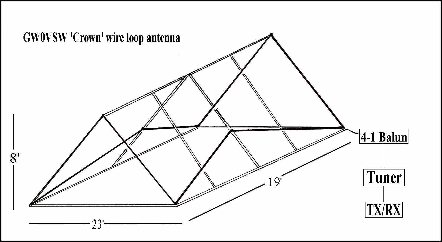
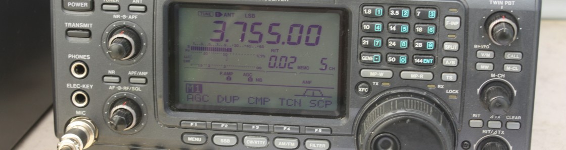
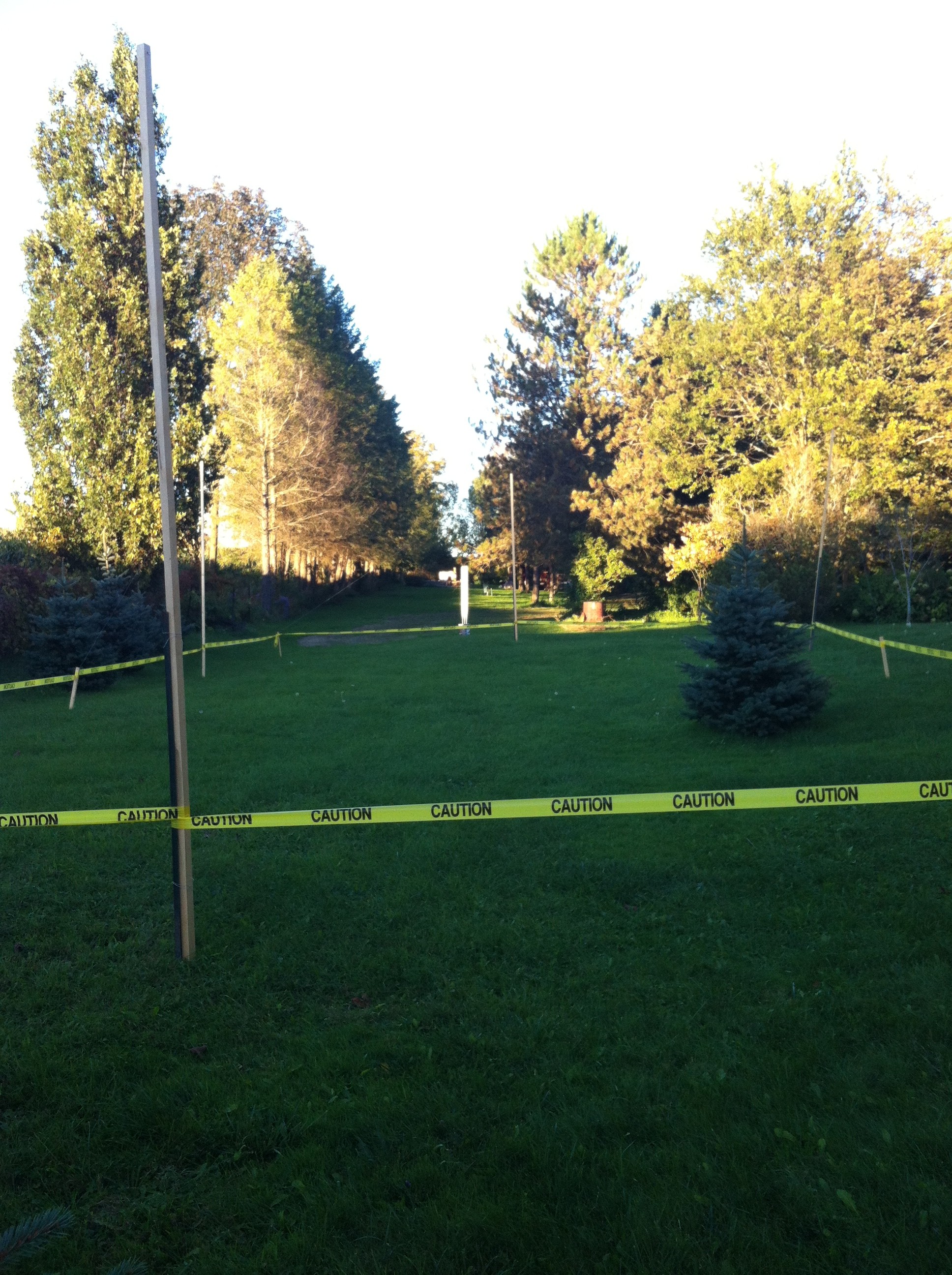
In order to experiment further with this type of antenna a new one was setup at Johan VA3JBO. This time the crown antenna was vastly expanded, it measures 68′ by 34′ (20.7 m by 10.3 m) and the low points are 2′ (0.6 m) of the ground and the high points are 12′ (3.66 m) of the ground. The total wire length is close to 245′ (74.7 m). The antenna is corner fed using a 4:1 balun and the coax cable used is a piece of LMR400 of 120′ (36.6 m) in length. The radio used is a Yaesu FT897D. Contacts were made to Washington state and Georgia during a recent contest. Both stations reported 5 over 9.
Friday, September 27. Three members came out Al VA3TET, Bruce VA3QB and Dennis VE3UTN were present and brought with them the field day radio (since this is a tried and true transceiver they felt more comfortable using it). Again several contacts were made as far away as Germany. This fellow came booming in as he was using 500 watts. After trying for several more hours it became apparent that the something had to be done to improve the radiating qualities of this antenna.
Saturday, September 28. Well Friday became Saturday and Dennis made a few more contacts. After some fruitless hours Dennis changed the feed point from the corner to the center of the long end (the antenna was fed from the north/east corner and is now moved to the south/east center). It apparently made some difference but not enough. Dennis was of course disappointed with the results (and he may not like it that I am telling) but he asked me to remove the pictures, however I believe that they should stay as this is what experimenting is all about. In the end they will tell a complete story.
Remarks. The next step is to square up the antenna so that we have equal sides of peaks and valleys. Meaning a 68′ by 68′ square.
Tuesday, October 01. Changed the rectangle configuration to a square one. We now have an equal number of peaks and valleys on each side. Each section of angled wire measures 20′ in length and there are 16 sections, thus a total of 320′ of wire. I know that one side of the square is 2′ short due to my deck being there. For those mathematically inclined we have actually only 318′ of wire.
We now have to wait for radio to be back here and then we can continue testing. The loop is still center fed. So can change one more parameter (connecting to a corner) and then I guess we are at the end of our song.
Wednesday, October 02. Reconnected the balun and connected the antenna to the transceiver. Not much going on around 14:00 – 15:00, tried again at 17:30 and got a hold of someone in Sao Paulo, he repeated my call sign but then conditions worsened and could not get him back. Pity. Again at 19:00 and the airwaves were full with American stations, could not get a word in edgewise.
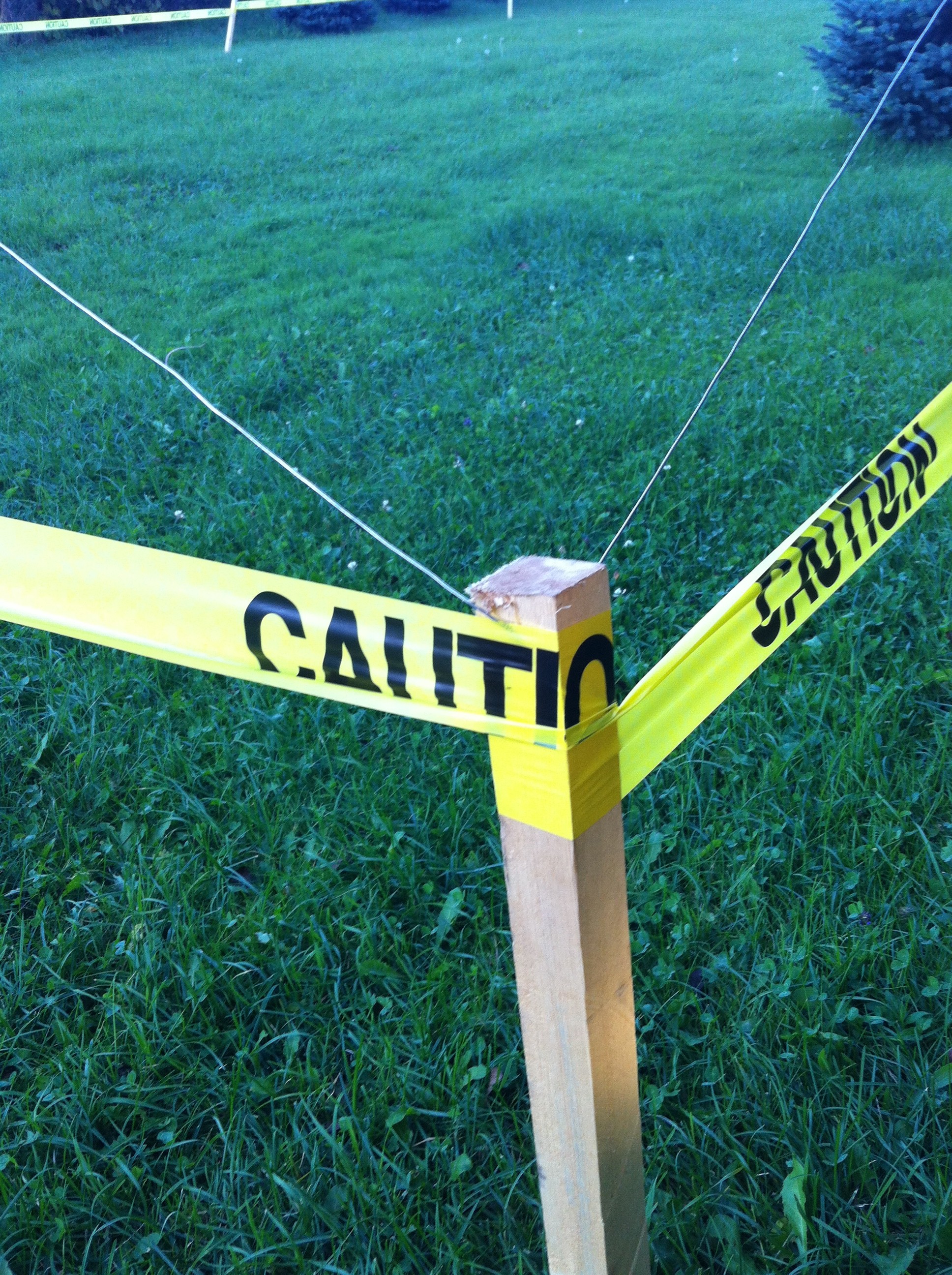
The valley is 2′ of the ground
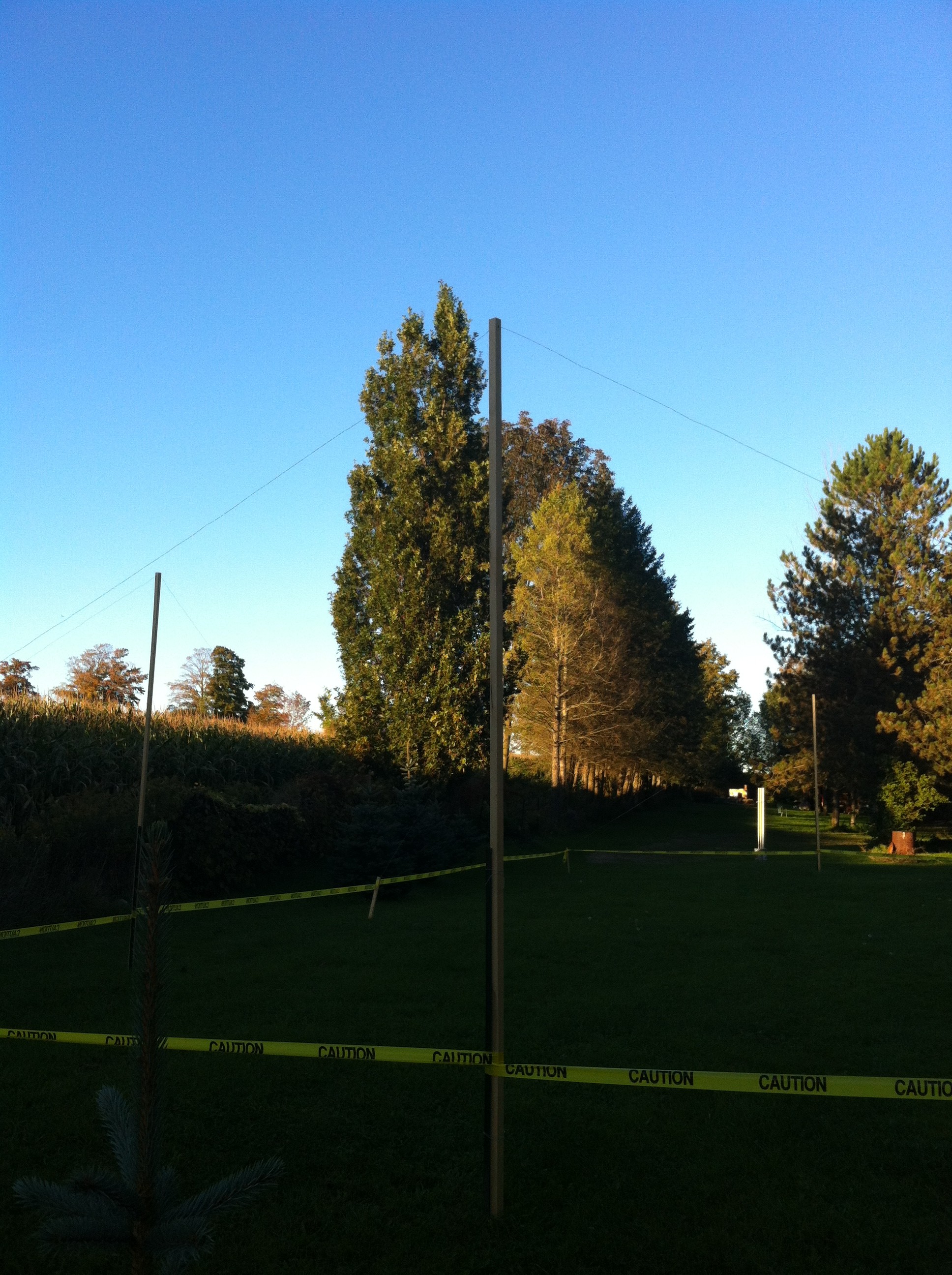
The peak is 12′ of the ground
- The area is: 4624 sq. ft.
All four sides now 68′