Antennas are never far out of the mind of an amateur radio operator. That is why this page will be dedicated to several different antenna design and also the development of the EH antenna. Our club has been instrumental to further develop the EH antenna. Alan MacDonald, VE3TET and Paul Birke, Ve3PVB have been busy with new designs and shapes of this promising antenna.
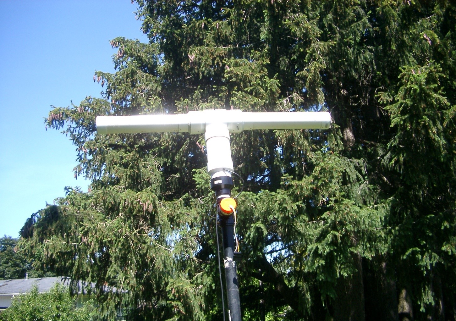
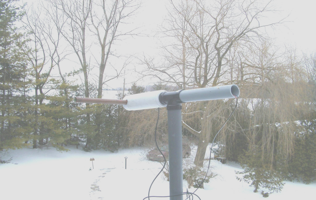
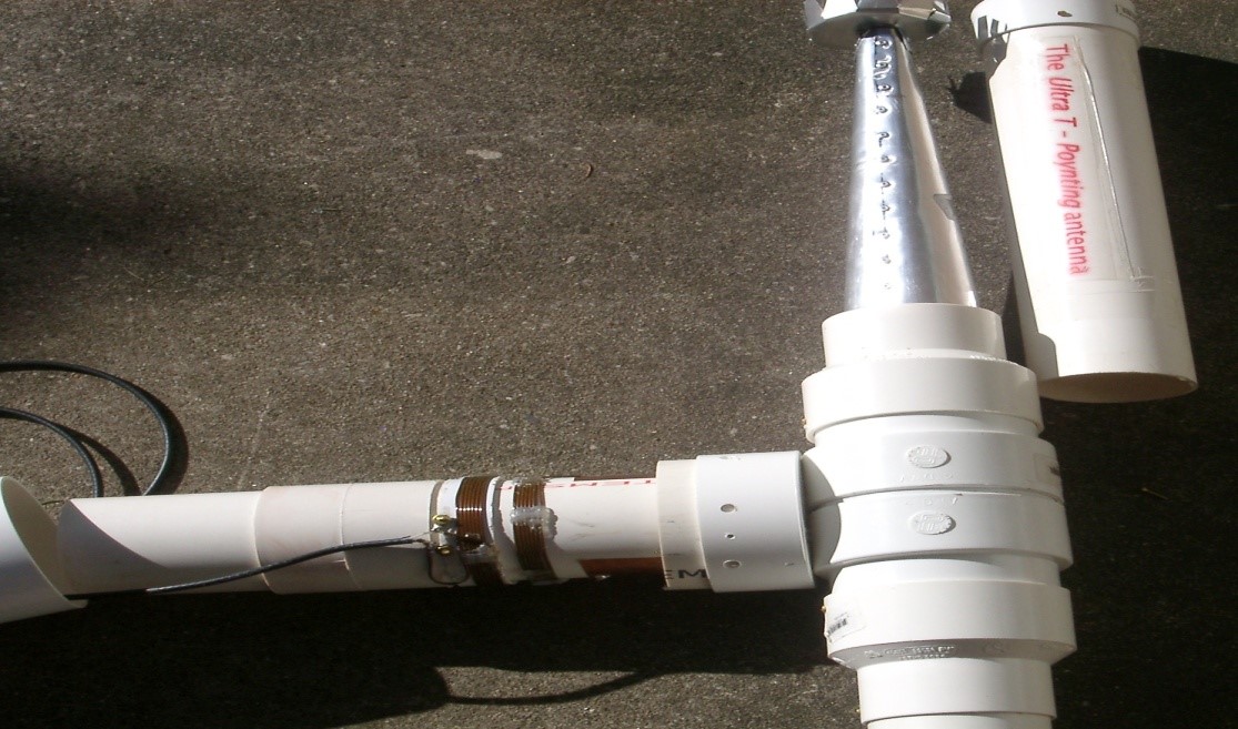
This is the UltraT Poynting Vector antenna
Total width is 36 inches for 20 meters and can be made smaller.
Circular polarization and QRM resistant.
Tunable High Q features acts as a Pre Selector.
Tunable across the band with 1.0:1 SWR
Usable is small spaces without a compromise in performance
Built from “off the shelf” materials.
The VE3ERC (Elmira Radio Club) Poynting Vector antenna evolution.
One of the few things that most Amateur Radio operators can do is build antennas. Most of us have at least attempted one or two with mixed success. There are lots of plans for building these mechanical/electronic wonders but most of them are variations on the half wave dipole or ¼ wave vertical. It is the intention of this brochure to provide you with the basic concepts of the PVA.
Our objective was to find an antenna that had the following attributes:
1 Very small foot print
2 Low SWR across the designated band
3 Very high efficiency
4 Omni directional (less prone to fading)
5 Capable of rejecting QRN
6 Built with readily available material
After searching the web, several articles of a “radical” very short antenna concept came to light. Names like Cross Field and EH antennas described how RF radiation was produced by applying existing theory in a novel innovative way. In fact, the EH antenna by Ted Hart seemed to fit the bill for a small, high performance antenna.
Ted Hart and others understood that if we could create the right electro-magnetic conditions, RF radiation will occur, even with very short radiators. At resonance, electrical and magnetic fields are at right angles to each other (Cross Fields), Poynting’s vector radiation would occur without long dipoles. Ted Hart saw John Henry Poynting’s 1884 theory in a new light.
Here is how the PVA works
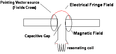
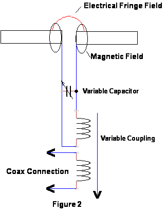
If we create an antenna where the gap between the radiators becomes the capacitance across a coil, at some frequency it should resonate. We also need to generated conditions to produce a fringing (curved) electrical field in the gap. This is done naturally. The electric fields not only go directly across the gap, they fringe around the gap. The electrical fields that go straight across are dubbed “dead capacitance” as they do not contribute Poynting vector generation. Magnetic fields travelling along the radiators are at right angles to the fringing E field (at resonance) around the gap. Where the electrical and magnetic fields cross, the Poynting vector (Radiation) occurs.
The configuration (Fig.1) in its simplest form satisfies the generation of Poynting vectors. Photonic radiation (electromagnetic radiation) occurs. You can deduce from the description that most of the radiation occurs around the gap where the magnetic fields cross the fringing electrical fields. This means that radiators longer than 5% of a wave length are of little use since the fringing electrical fields are almost non- existent. Usually these antennas are efficient with a dipole length of approx. 3% of a wave length. With the 3% rule applied, the antenna behaves as an isotropic radiator with circular polarization. This last property is very important, as unlike Hertz antennas, the Poynting Vector Antenna exhibits no fading.
Attempts to build this antenna resulted in impedance matching problems and high common mode currents. It relies on a tap on the resonating coil for an impedance match and is very difficult to get right. It usually occurred about a half turn from the bottom of the coil- even a 1/8 turn off will cause a large mismatch. The antenna also had no isolation from the coax, so coax length would affect the tuning. – In other words, it was a bear to tune. Early attempts to build this antenna usually resulted in failure, and generated comments like “the coax is a better radiator that the antenna”.
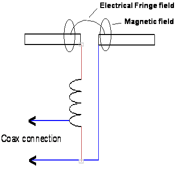
Figure 1
The problem was not the theory. It was an impedance match and common mode current problem. After building several of the suggested original designs and testing them, we concluded that a different approach was in order if we were to take advantage of Poynting’s theory.
Please keep in mind that all of our efforts started back in 2001. We felt that the theory was correct, but the implementation was certainly not. After an analysis we concluded that isolating the antenna from the coax feed would help reduce common mode current, and implementing variable coupling and a balanced/resonating feed for the radiators would ensure that we created the right conditions for Poynting vector production. The SuperT (See fig.2) was born.
Materials used to construct the antenna consisted of PVC plumbing with a few pieces of acrylic plastic for spacers. It was our intent to completely enclose the workings in PVC to provide weather protection. The metal radiators were 1 inch copper pipe and 14 gauge copper wire was used for the coils.
It turns out that PVC is a pretty good insulator for powers up to 100 watts
The SuperT – 100 watt antenna.
This was the configuration employed to overcome the nastiness.
Link coupling was introduced to isolate the antenna from the coax and the coupling and turns ratio of the coils was used to optimize the impedance match and control SWR.
Note: the secondary winding is part of the resonant circuit using the capacitance of the gap to complete the resonant circuit. There is an interaction between the primary and secondary because of the close coupling of the two coils. Our approach was to resonate the secondary coil to the lower middle part of the band first, and then introduce the primary. Since there is mutual coupling between the coils, the resonant frequency of the secondary coil will rise as a result of the coupling (the primary and secondary are partially coupled in parallel resulting in a slightly lower inductance in both coils). A little trial and error will be needed to find the correct resonance and lowest SWR by adjusting the spacing between the coils and the turn’s ratio. Try to keep the spacing between the coils to less than ¼ inch to ensure good coil coupling. We used a dipole gap of ½ inch to reduce arc over potential between the radiators. The antenna would have to be redesigned for higher powers. The materials used and spacing’s would have to change. This is a high Q antenna so high voltages occur at resonance.
Band width measurements showed that we had a high Q antenna that did not cover the band (in this case 20 meters). We added a simple home brew variable capacitor to enable tuning across the band with a constant 1.0:1 SWR.
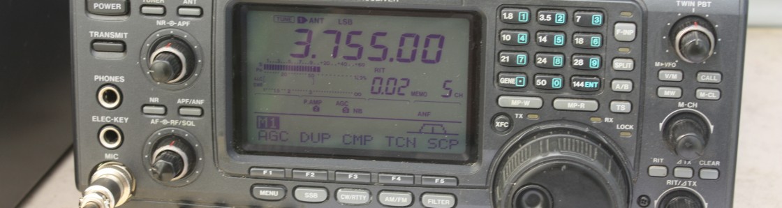
Remote tuning was accomplished by using a small DC gear motor to turn the home brew capacitor. The antenna became a pre-tuner for the receiver and resulted in a lower noise, among other benefits. Even with coil interaction, the SWR and tuning adjustments were straight forward.
There is no evidence of common mode current or coax radiation problems.
An early version of the SuperT
We built 10 SuperT’s and several are still in use after 12 years.
This approach worked, but subsequent information has helped us with a better approach to impedance matching and understanding of how to optimize.
12 years later and a few more grey hairs
Enter Paul Birke (VE3PVB), a retired engineer who had discovered the EH antenna on the internet. He contacted Ted Hart, the patent holder of this antenna.
Paul mentioned at one of our radio club meeting that he had discovered this really small antenna EH antenna that Ted Hart was promoting. I told Paul that we had tinkered with them some 12 years ago and had found a way to tame the beast. After review, Paul was surprised we had not published the antenna information as it was a successful solution to some of the ongoing problems. This information was also shared with Connie Winrod in Sweden who was experimenting with different approaches to build and understand the PVA. Ted Hart also liked the link coupled approach to building the antenna.
Paul, Ted, and Connie were trying to describe the EH antenna theoretically. Over the next two years (2012-2014), many of the secrets of this antenna have been revealed. A scholarly book is in the works for those of you that want all the theoretical details.
There are a plethora of approaches to generate Poynting vectors, but we will concentrate on the Elmira Radio Club’s evolution to the UltraT Poynting Vector Antenna.
The evolution to the UltraT Poynting Vector Antenna
There were a lot of unanswered questions about how to optimize the antenna.
Some are listed below:
1 What is the impedance of the antenna?
2 What shape should the radiators be?
3 Gap shape for optimum electrical fringe field production?
4 What is the configuration for optimum receiving?
5 High or low Q?
6 Increased tuning range for multiple bands
7 Potential for even smaller footprint
8 Potential for “mini beams”
What new information is now available and how do we implement it?
Let’s start of by acknowledging the contributions of Paul Birke. His theoretical insights have moved this antenna’s status from mystery to a mathematical model.
The Radiator shape:
Paul was investigating the fields around the gap and realized that the shape of the radiator would aid in the production of radiation. He was looking at how to get the best transfer of energy from the antenna surface to free space. (The free space impedance is 377 ohms). Paul determined that a curved surface (egg shaped) or a wine flute glass shape had the desired cosine curve. This curved shape helped with matching the antenna’s radiation to free space. If you want the math to prove this, buy the pending book.
A new commercial Flute (trade mark) antenna employs the result of the latest design information. That leaves “we poor DIYS antenna constructors” with a difficult shape (wine flute) to build. The closest approximation that is easy to make would be a cone. It turns out the cone is a very close approximation to flute shape with very little reduction in performance. We can now take advantage of one of the improvements with homebrew construction.
As you can appreciate, the diameter of the radiators at the gap and the gap spacing will determine a major portion of the capacitive reactance at the frequency of operation.
As you increase the radiator length beyond about 4%, the antenna does start to take on some directivity of a dipole. This will be another area of investigation.
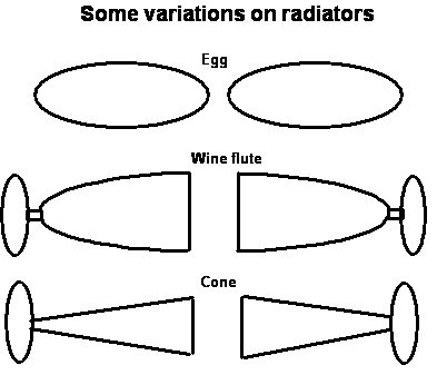
Note that the disks shown on the flute and the cone are the antennas termination to free space.
Impedance matching of the antenna to the coax: Here again, Paul determined that the gap spacing, diameter of the radiator at the gap, and frequency of operation will determine the actual impedance of the antenna. The gap spacing and diameter of the radiator are related to the capacitive impedance and radiation resistance. Paul has provided a table to help with this determination and relieve us of the math. This information is for 100 watt transmitters.
Knowing any two of the variables g, Do and Rr allows determination of the third. Of course, at times some interpolation may be needed.
Notice: We do not advise any gap greater than ~ 1″ as any value above this limit, can reduce the magnetic field strength in the area of the gap. This can cause a decrease in the intensity of the Poynting vector generation on the gap centre line. Using this gap rule ensures the antenna is producing the maximum radiation for the given design.
A good design Rule of thumb: radiator diameter should be 1/3 the length of the radiator. The radiator length should be 3% of a wave length.The ARRL hand book has the wave length formula.
PVA MEMORANDUM 3 REV.0 21 MARCH 2014
DESIGN CHART OF GAP g FOR MAXIMUM RADIATION for FLUTE or Cone Shaped PVA’s
Here is our design chart showing the relationship between FLUTE’s or Cone’s gap g, diameter Do and the radiation resistance Rr.
Once you have determined the radiation resistance, you can determine the primary (50 ohms)/secondary (from table) turns ratio. The ARRL handbook deals with this.
![]()
High or low Q (This is an issue close to my heart.)
Most amateur modern radio transceivers do not have a tuned front end on the receiver. The consequence of this approach is the mixer receives a very broad band of signals including powerful AM broadcast, TV and an assortment of other undesirable RF signals. The mixer attempts to take the signal you want and present it to the IF section of the receiver. As you can appreciate, a mixer could be easily be pushed into an overload region of operation when overpowered. This condition will generate artifacts of the unwanted signals and contribute to a raised noise in the receiver. Weak signals then become more difficult or impossible to hear.
An argument for the high Q antenna:
If we were to provide a filter at the antenna, we could greatly reduce the artifact content at the mixers. If it were a high Q filter, it would reduce the mixer artifact content even more, therefore decreasing the ambient receiver noise. We took the high Q approach to enhance the receiving capabilities of the antenna.
The problem with high Q is narrow band width. Our solution was to remotely tune the antenna with a home brew variable capacitor driven by a small gear motor. Now we have a Pre-Selector at the antenna. This antenna receives what it is tuned to, and rejects the rest.
Low Q:
When we design the antenna for low Q, we allow more noise to reach the receiver because of the wider bandwidth. Experimenters have taken the low Q approach and have simpler construction. They don’t need a remote tuner.
We elected to go with the advantages of Hi Q.
Receive Optimization:
One of many unresolved issues with this antenna is optimizing the receive characteristics. We have dealt with high Q, but not radiator length for receiving. A very basic rule of receiving antennas is to maximize its exposure to RF signals. RF energy is intercepted by metal conductors. The larger the surface area, the better is the potential for collecting a signal. This could mean that even though the Poynting Vector Antenna transmission length capabilities have been optimized, the receiving capabilities could be enhanced independently. We already know that longer elements take on receiving directivity. More work to be done! Reciprocity may be in jeopardy!!!! The other items on the wish list are still being addressed
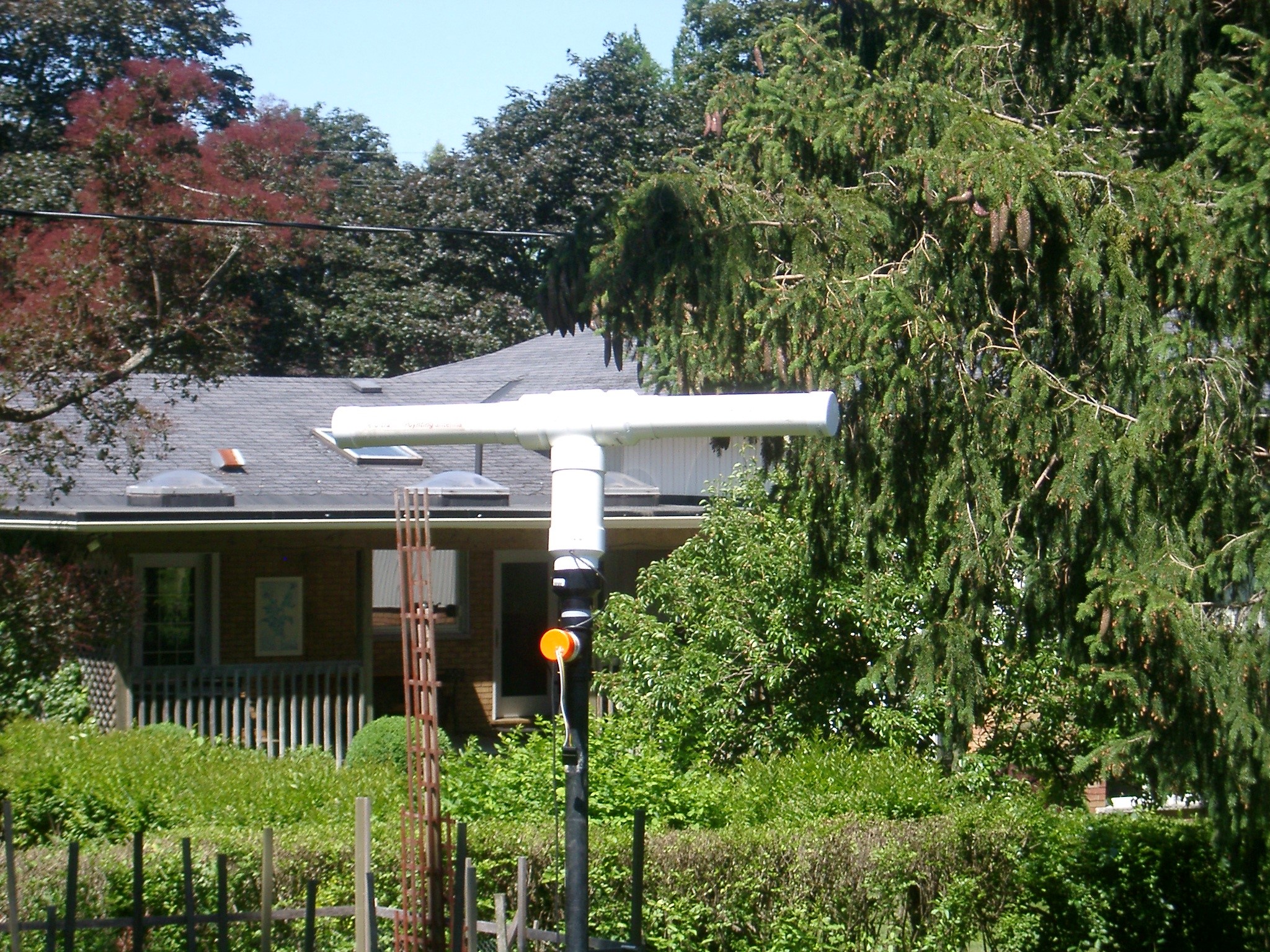
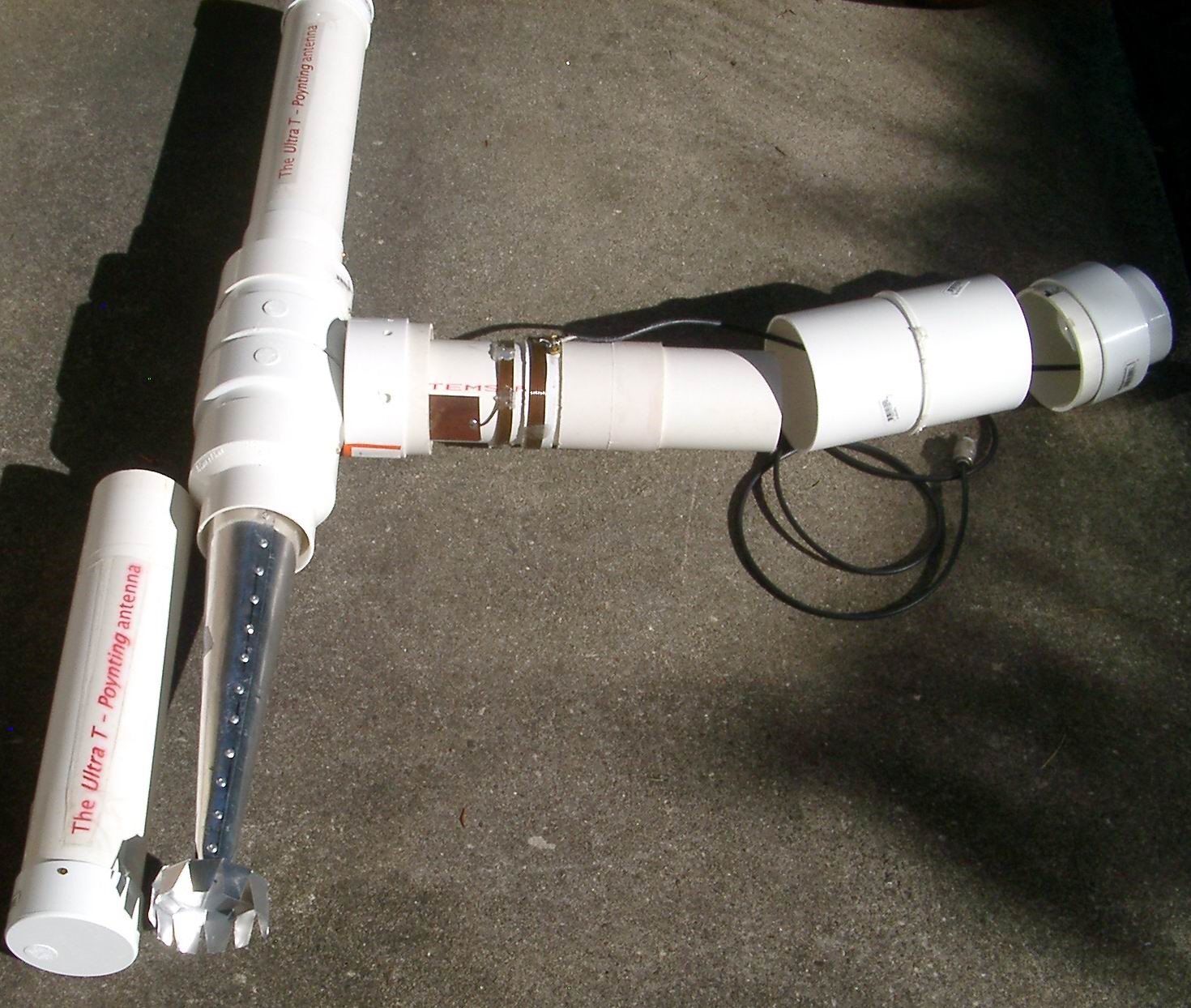
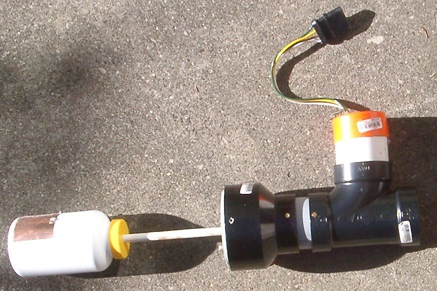
This is what the UltraT looks like when it is fully dressed.
The orange cap provides access to the motor
Here are views of some of the construction with a few notes. Detailed drawings are in the works.
![]()
The cone was constructed from aluminum flashing using pop rivets to secure the edge. We made a wooden form on a wood lathe to help with the forming. A ¼ inch acrylic disk was cut to just fit inside the cone for support and mounting. The white threaded nylon rod is a toilet seat bolt. The opposite cone has a plastic disk also. Both disks are threaded to match the nylon bolt. This facilitates mounting. Note the disk mounted at the skinny end of the cone for E field sinking.
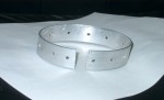
The .75 X 1/16 inch metal ring is mounted over the cone at the gap end and pop riveted. It allows a secure electrical connection to the cone and provides a way to better distribute power around the cone.
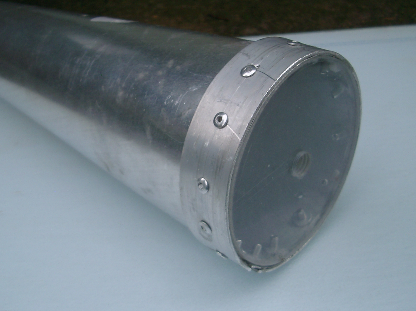
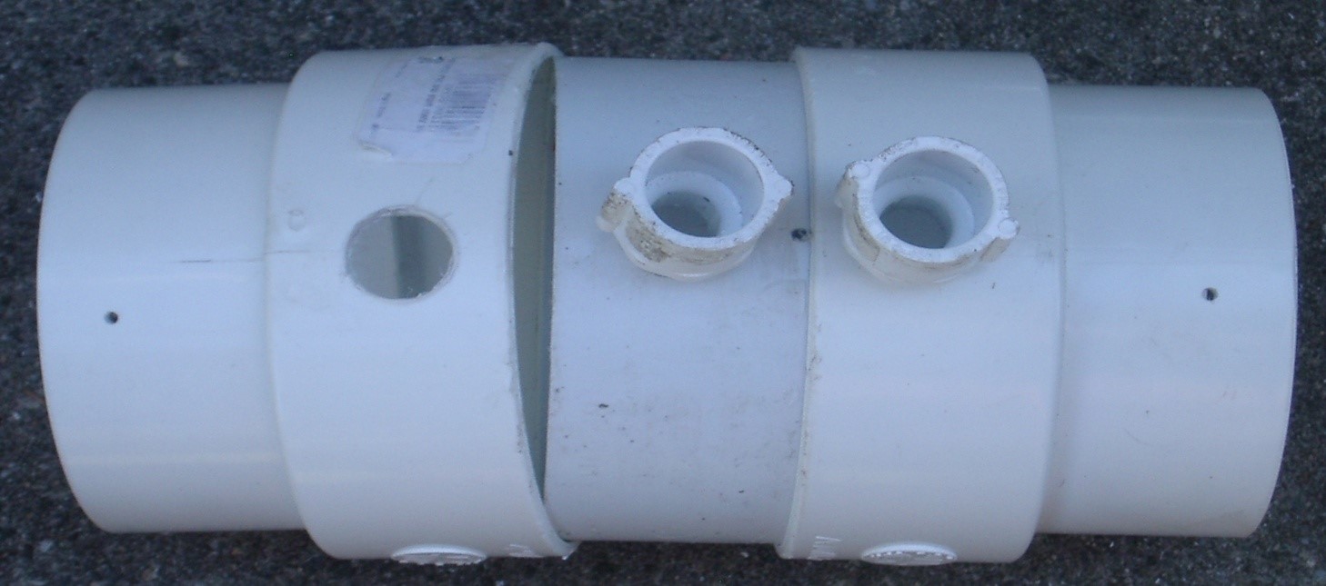
Image of one of the spacers inside the 4 inch PVC coupler. One spacer is mounted on each side of the stop flange and the nylon bolt on the cone is passed through the spacers. The cones are then screwed together. This secures the cones to the coupler.
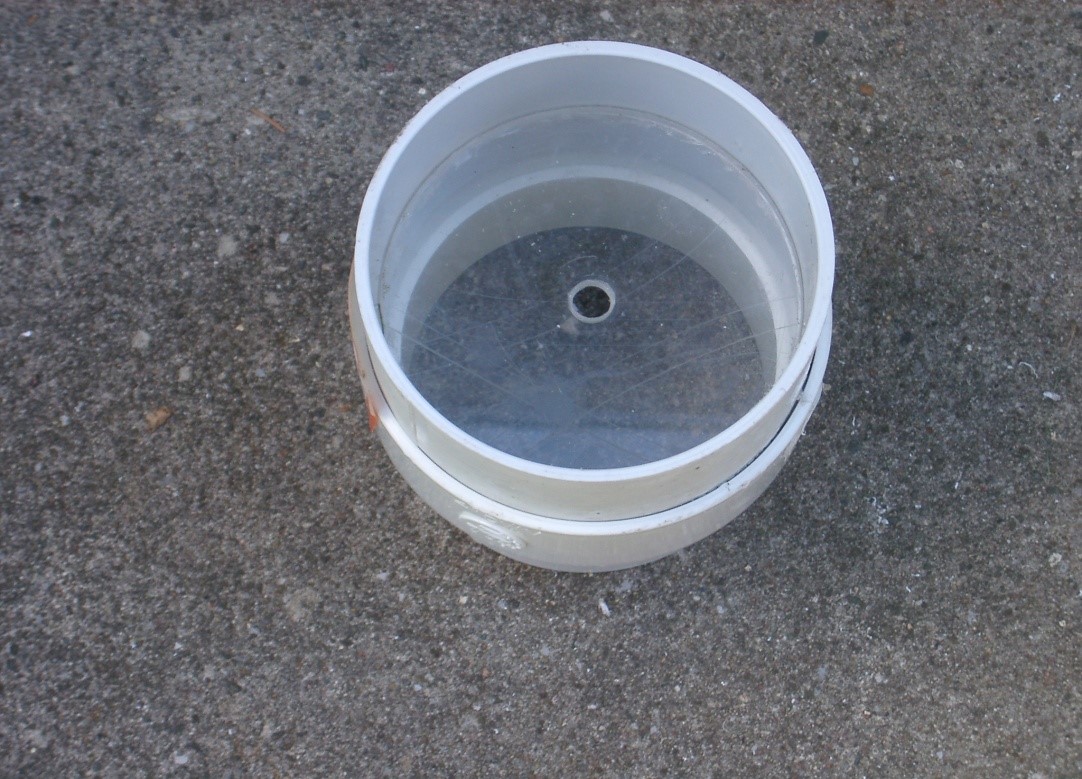
Use the guide Paul provided to select the spacer thickness. The thickness of the spacers and the stop flange will give you the gap dimension. Material for the spacers can be PVC, Acrylic, Polyethylene, Teflon, Glass, and other suitable isolative materials that are not hydroscopic.
We used Acrylic and Polyethylene with good success.
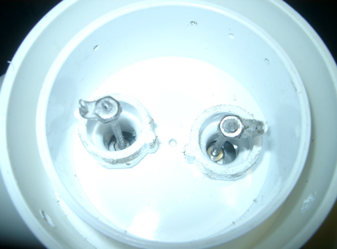
After drilling holes through the assembly (below) and threading the holes for ½ inch PVC water pipe couplings this assembly is ready for the cones. Mount the cones and use a marker pen to mark the location of the center of the hole on the metal flange of the cone (through to water pipe couplers). Drill and tap. We used 6:32 threads. Thread pieces of aluminum wire and cut long enough to thread into the cone and clear the top of the water pipe couplers. This is how we connect to the rest of the antenna.
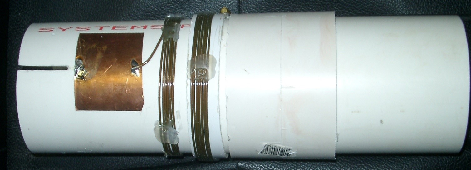
This is a view of the primary and secondary (resonant) coils. Note that the resonant coil is directly connected to the capacitor copper foil. There is another foil at 180 degrees. The slot allows the wiring on the cones to be connected to the copper foils. This completes the resonant circuit. The primary coil is wound on one half of a 3 inch coupler. The coupler will slide to facilitate coil spacing allowing simpler final SWR and tuning adjustments.
Above is one of our improvised capacitors that slide’s into the pipe the coils and copper foils are mounted on. The foils on the rotor part of the capacitors are wired together. You also get a view of the motor housing and plastic shaft. (The labels are not a requirement).
A construction note: PVC pipe is a good material to use if it is clean. It is good practice to wash all parts and rinse well. Dirty parts cause arcing, — we have done it! Hi Q antennas produce high voltages!!
The results of Rev.1 version of the UltraT testing
We tested the performance of the UltraT version against a 20 meter dipole specifically to length of the transmitter frequency. Both transmit and receive antennas were mounted at 30 feet. A small 100 mw crystal controlled transmitter was used as a signal source at a distance of approximately 1000 ft.
A 20 meter dipole was constructed and tuned to the transmitter frequency. This was used as a reference.
20 meter dipole PVA 20 meter antenna
Noise floor -103dbm -107dbm
Received amplitude -60dbm -72dbm
90 degree rotation -75dbm -78dbm
Notice that the 90 degree rotation amplitude on the PVA only changes by 8dbm verses 15dbm for the dipole. The PVA, even with the dipole length of 4.5%, still gets close to the radiation characteristics of an isotropic radiator. Shorter radiators (3%) make the PVA Omni directional.
A subjective listening Test:
Even though the signal strength was lower on the PVA, we could still copy all the weak signals heard on the dipole. In fact, the PVA was able to provide better readability on weaker signals adjacent to strong stations because of its much narrower bandwidth and lower noise floor. The PVA is also less susceptible to QRN because individual electrical and magnetic fields inherently cannot produce Poynting vectors, hence very little QRN gets through. Because the PVA is inherently has circular polarization, the antenna does not exhibit fading. Ongoing research will continue to improve the performance of this mighty midget, and it appears that gains will match that of a dipole with some of the developments that are in the works.
New applications for the PVA
How many of you have dreamed of a way to get on 80 or 160 meters? This antenna will fit even the smallest back yard or a balcony.
As most of you know, RAC has been active in securing approval for two new bands in the very low frequencies (below the broadcast band. When these bands are available, the PVA antenna will be an attractive solution because of its small size and performance. Considering that a PVA antenna length needs to be only 1-3% of a wave length, this antenna is the answer for back yard installations.
QRN and QRM are particularly high on lower frequencies. The PVA can’t hear most of it because most natural and manmade noise is not in phase. Only in phase RF produces output.
You can also go small for VHF and UHF. These frequencies make the PVA a great choice for hidden or stealth installations.
Rev1.1 is being used for June 1/2014 demonstration with some of the improvements incorporated.
The Elmira Radio Club will be building the latest 20 meter version in the fall of 2014
The information provided is intended to help you to understand why and how this antenna works and the advantages it provides. Ongoing research will continue to improve the performance of this antenna.
Stay tuned — UltraT Rev1.2 will supersede Rev1.
Al Macdonald (VA3TET)
For the Elmira Radio Club (Poynting the way!)
Copyright April 23/2014
Many thanks to Paul Birke (VE3PVB and Terry Maurice (VE3XTM) for their editing and technical advice.